Building Seismic Loads can be automatically generated according to the equivalent static methods of the following codes:
Seismic load can only be applied at diaphragm/floor levels. The program will automatically calculate the center of mass and the 5% accidental eccentricity for the various seismic load cases. If a greater eccentricity is desired, it may be specified in the Diaphragms spreadsheet in RISA-3D.
Note
The Seismic Weight of each
The self weight of the structure includes the deck, all gravity and lateral members, and all walls. While computing the seismic weight of each floor diaphragm, the column and wall weights in each story are equally distributed to the floors above and below the story. These items can be manually excluded from the seismic load by un-checking the desired elements on the Seismic tab of the Model Settings Dialog. For more information on these exclusions refer to the Model Settings - Seismic.
Note:
The program does not include all applied loads as part of the seismic weight. The only applied loads that are included are the ones assigned to the Load Category called "Dyn Mass". The super-imposed dead loads (PreDL or PostDL) are not included. The reason for this exclusion is due to the fact that the super-imposed dead load is often a very conservative number (accounting for the inconsistencies and unknowns in the construction process). That load may be overly conservative for the calculation of seismic weight.
Therefore, the user must specify a "Dyn Load" or "Dyn Mass" for each Area Load, Line Load, and Point load that they apply to their structure. This "Dyn Mass" represents the additional load (above and beyond self weight) that must be included in their calculation of Seismic Weight.
Note:
For additional advice on this topic, please see the RISA Tips & Tricks webpage at risa.com/post/support. Type in Search keywords: Dyn Load Category.
The total seismic weight of the whole structure is the sum of the seismic weights associated with all
The seismic force is calculated for each diaphragm only. Therefore, any seismic weight that is not connected to diaphragms at all (e.g. walls located outside of a slab edge) will not be included in the seismic force distribution.
Note:
For additional advice on this topic, please see the RISA Tips & Tricks webpage at risa.com/post/support. Type in Search keywords: Diaphragms.
The parameters used in the seismic calculations may be viewed or changed on the Seismic tab of the Model Settings. These settings may also be changed or manipulated when changing from the RISAFloor interface to the RISA-3D interface.
For additional advice on this topic, please see the RISA Tips & Tricks webpage at risa.com/post/support. Type in Search keywords: Generate Seismic.
Seismic Code currently allows you to choose the code which will be used for seismic load generation. For reference, sections of the 2022 edition of ASCE 7 will be cited to explain the various entries.
T represents the input natural periods in each lateral direction. These would typically be determined from an eigensolution analysis. If these values are not entered, then the program will calculate this using the Approximate Fundamental Period as defined in section 12.8.2.1 of ASCE 7-22. This value is entered for each of the Global horizontal directions.
Ct is the building period coefficient as defined in 12.8.2.1 of ASCE 7-22. It is used in conjunction with the Ct exponent "x" to determine the Approximate Fundamental Period. These are defined for each of the Global horizontal directions.
Note:
R is the Response Modification Factor as defined in table 12.2-1 of ASCE 7-22. It provides a reduction for the design seismic force based on the ductility of the system. This is defined for each of the Global horizontal directions.
Note:
Base Elevation determines the height at which the structure is assumed to be connected to the ground. This is important for hillside structures or structures with sub-grade floor levels. A certain amount of structure self weight may be associated with base level (or sub-grade levels) of the structure. The Add Base Weight check-box determines if that self weight will be added into the base shear to be distributed as lateral force through the height of the structure per section 12.8.3 of ASCE 7-22. If no elevation is chosen for base elevation, then the lowest joint in the structure will be assumed to be the base elevation.
Risk Categoryis used to determine the importance factor assigned to the structure per table 1.5-2 of ASCE 7-22.
S_D1 represents the 5% damped spectral response Design acceleration for a 1.0 second period.
S_DS represents the 5% damped spectral response Design acceleration for short period response.
S_1 represents the 5% damped spectral response Mapped acceleration for a 1.0 second period.
TL represents the point at which the structural response is assumed to transition from a velocity controlled response to a displacement controlled response. These values are shown on Figures 22-14 through 22-17 in ASCE 7-22.
Response Spectrum allows the user to choose between a two-period response spectrum or a multi-period response spectrum. This option is only available when the code selected above is ASCE 7-22.
Note:
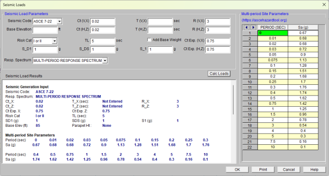
When Multi-Period Response Spectrum is selected, the seismic load generator dialog shows the Multi-Period site parameters spreadsheet. This spreadsheet matches the parameter input based on ASCE 7-22 Section 11.4.5.1. When this is selected the user must input all 22 data points in ascending order with the last data point having a period of 10 sec. When two-period response spectrum is selected the seismic load generation follows ASCE 7-22 Section 11.4.5.2. This section is similar to the response spectrum found in older versions of the ASCE 7 code.
When you activate RISA-3D via the Director Menu, the program will calculate the appropriate seismic loads and present the calculations in a printable report. You may open the seismic load generator at any time to view, print, or recalculate the seismic loads. When you change something in the RISAFloor model that changes the seismic loads they are automatically updated the next time you enter RISA-3D.
This section displays the user all the relevant design data entered so that it can be included on print outs with the Seismic Load results.
This section reports the values used to obtain the Base Shear in each of the two global directions.
T Used is the period which was actually used to determine an upper limit for Cs in equations 12.8-4 and 12.8-5 of ASCE 7-22 (if applicable). A user defined period can exceed the upper limit period.5
T Method A is the approximate period calculated per equation 12.8-8 of ASCE 7-22.
T Upper Limit is the maximum allowable period to be used in equations 12.8-4 and 12.8-5, calculated per Table 12.8-1 of ASCE 7-22.
Importance Factor is determined from Table 1.5-2 of ASCE 7-22, based on the specified Risk Category.
Design Category is determined in Section 11.6 of the ASCE 7-22 and reported here.
V (Base Shear) is calculated using the Governing Equation listed next to it.
Governing Equation is the equation which was used to calculate the base shear. This is typically from 12.8 of ASCE 7-22.
Cs is the seismic response coefficient used to calculate the seismic base shear, V.
This section displays information used in distributing the seismic force to each diaphragm or story level. This includes the calculated Height and Weight of each diaphragm, the calculated Force in each horizontal direction and the calculated location of the Center of Gravity of the diaphragm (CG).
Note:
This section displays information used in calculating the accidental torsion values. This includes the Width and Length of each diaphragm and the distance used for the accidental eccentricity.
Note
When running a combined RISAFloor/RISA-3D model the program has the ability to create Semi-Rigid Seismic loads and apply them to the diaphragm. The seismic load is calculated by taking the Total Seismic Weight and converting it into a horizontal direction by multiplying by the seismic response coefficient Cs.
The program will apply a Diaphragm Surface load which represents the seismic contribution of the Slab weight and any additional Dyn Load. There will be horizontal point loads and line loads at the top of the columns and walls which represent their respective contribution of the seismic weight. Any point, line or area loads that are "Dyn Mass" will also be converted as horizontal seismic load applied directly to the diaphragm. Below shows an example of the Earthquake loads applied into a simple L-shaped building.

Note